To help us provide you with free impartial advice, we may earn a commission if you buy through links on our site. Learn more
- Make a multiroom audio system - part 1
- Getting started
- Wi-Fi Hi-Fi
- Squeezebox
- Setting up your Raspberry Pi
- Set up Squeezelite
- Running Squeezelite on startup
- Quality control
- Clone yours
- Make a Raspberry Pi smart doorbell
- What you need
- Install Pushover
- Soldering the wires
- Make it wireless
- Overkill?
- Make a video intercom system
- Your call may be recorded
- Who's at the door?
- Linking up and limitations
- Make a Raspberry Pi CCTV security system
- Remote control
- In motion
- More on Motion.conf
It’s the spiritual successor to the Sinclair Spectrum. The ultra-cheap yet amazingly powerful barebones computer that’s perfect for a thousand and one different projects.
We love the Raspberry Pi, and there’s so much more to it than a just a cheap Linux PC for web browsing and email. Thanks to the Pi’s GPIO (General-Purpose Input/Output) pins and the powerful Python programming language, you can turn the unassuming circuit board into a multiroom audio controller, video intercom system, time-lapse camera… given time, ingenuity and the will to plug electronic components into a breadboard, the possibilities are endless.
In this article we’ve gathered some of our favourite Raspberry Pi projects, to help you get the most out of your £30 mini wonder. Get set to unleash the power of Pi.
Make a multiroom audio system – part 1
Save money and boost your geek credentials by putting together your own wireless audio system
Multiroom audio systems are a must for music lovers. You can listen to a song in the kitchen and you don’t need to do anything to enjoy the same track as you move into the dining room for your meal. You can control playback from your smartphone or tablet, or even set different moods for different rooms at a house party by playing a funky playlist in your living room and a calmer selection in the kitchen. The problem is, many multiroom audio systems install a secondary wireless network, and the speaker units can easily cost £300 each. By using a Raspberry Pi, your own wireless network and a NAS or PC as a server, however, you can make your own high-quality wireless speaker units for around £100 each.
Getting started
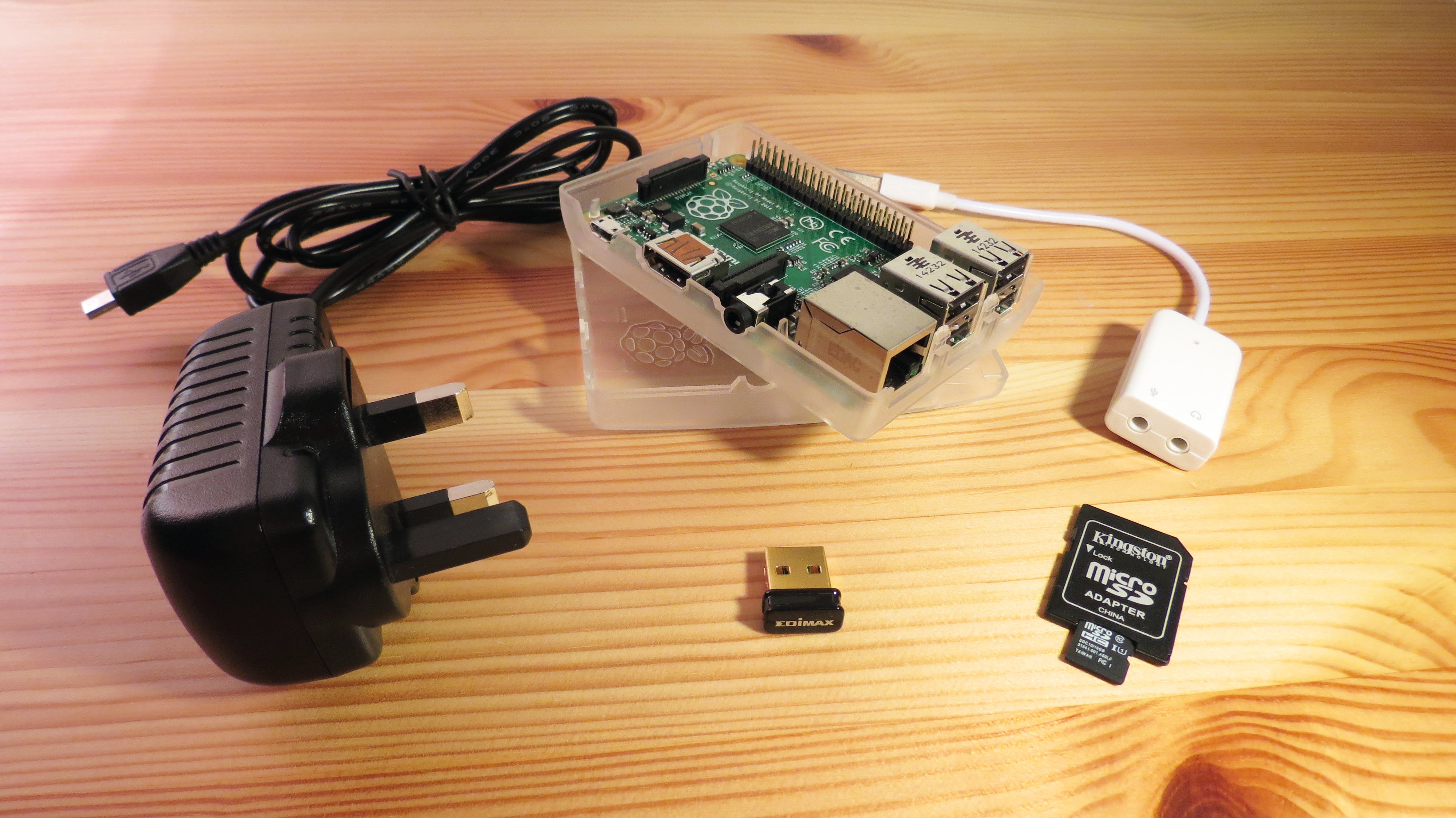
As the basis for the system we’ve chosen Logitech’s Squeezebox NAS software (also known as Logitech Media Server, a common app on most NAS units) and a Raspberry Pi. We used a Raspberry Pi 2, as it has four USB ports. You’ll need these ports as for this project we’ve decided to use a USB sound card; the crackly integrated Pi audio output just isn’t good enough for music. We chose to use a simple £3 USB sound card bought from thepihut.com as it does the job and is natively supported by the Raspbian operating system. However, you could use a fancy USB sound card such as Creative’s Sound Blaster Play! See here for a full list of Pi- compatible USB sound cards and installation instructions. The other ports will be taken up with the Wi-Fi dongle (see below) and a keyboard and mouse for setup. You could, of course, use a USB hub to set up a two-port Pi.
| Raspberry Pi 2 Model B | £30 | www.currys.co.uk |
| 8GB microSD card | £2 | www.ebuyer.com |
| Power supply | £5 | http://thepihut.com |
| Wi-Fi dongle | £6 | http://thepihut.com |
| USB sound card | £3 | http://thepihut.com |
| Multicomp clear case | £5 | http://thepihut.com |
| Creative GigaWorks T20 Series II speakers | £85 | www.currys.co.uk |
| Total cost | £90 |
We chose Edimax’s EW-7811Un Wi-Fi dongle as it’s tiny, only £6 and is natively supported by Raspbian, so we won’t have to faff around installing a driver. Other Wi-Fi dongles are also natively supported by Raspbian; any shop-branded dongles from www.modmypi.com or http://thepihut.com will be fine, and there’s a full list of compatible dongles. Although specialist Raspberry Pi resellers sell microSD cards pre-loaded with Raspbian, it’s easy enough to install it yourself on a cheap card. We chose an 8GB Class 10 microSD card and SD adaptor, which cost just £2 from Ebuyer.
We used the cheapest clear case we could find for our Pi B+, which was Multicomp’s Clear Case at £5. Clear cases let you see the Pi’s power and activity lights, but to reduce light pollution in your living room, you could use any case you like. You could even build a case from spare Lego to house the USB sound card neatly and hide the Wi-Fi dongle’s flashing activity light. As the Wi-Fi dongle is power-hungry, and the Pi is powering a USB sound card as well, opt for a 2A power supply. Modmypi.com and Thepihut.com sell such supplies for a fiver.
To round off your speaker unit, you’ll need speakers. Creative’s GigaWorks T20 Series II is a high-quality set of powered stereo speakers, but you can use any 2.0 or 2.1 speakers you like as long as they have their own power supply. Our shopping list shows the parts for a single wireless speaker unit; for a multiroom audio setup, you’ll need one set per room.
Wi-Fi Hi-Fi
Whichever speakers you choose, the build process starts by downloading the latest version of Raspbian, as well as SD Formatter 4.0, Win32DiskImager and PuTTY. While Raspbian is downloading, you could put the Pi in its case.
Once downloaded, extract the Raspbian image from its zip file. Put the microSD card into the SD adaptor and insert this into your PC; wipe the SD card with SD Formatter and then install the extracted Raspbian.img file on to the SD card using Win32 Disk Imager. Once Raspbian is written to the SD card, take the microSD card out of the SD adaptor and insert it into the Pi. Next insert the Wi-Fi dongle and a USB keyboard, then plug in the Micro USB power adaptor.
Log into the Pi with the standard credentials (pi, raspberry) and then type ‘sudo raspi-config’. Hit Enter to select the first option, Expand the filesystem. Once the Pi tells you the file system has been expanded, change the password (option 2) by pressing down arrow, Enter and following the instructions. Exit and reboot the Pi by pressing the right arrow twice and hitting Enter.Log in again and you’re ready to set up the Wi-Fi dongle. Edit the wpa_supplicant config file by typing ‘sudo nano /etc/wpa_supplicant /wpa_supplicant.conf’ and pressing Enter. Add the following at the end of the file (using your SSID and Wi-Fi password, remembering that you’ll have to use your 2.4GHz network unless your Wi-Fi dongle is very fancy):
network={
ssid=”your_ssid”
psk=”your_password”}
Save and exit by pressing Ctrl+X, Y and then Enter. Check the change works by typing ‘sudo reboot’, log back in once the Pi has rebooted and then type ‘ifconfig’ to display the Pi’s network settings. You should see a section for ‘wlan0’ and an IP address that’s in line with other IP addresses on your network, probably something like 192.168.1.xxx.
Before updating your Pi you should uninstall Wolfram Engine, as this can interfere with this project, isn’t required and massively slows down the updating process. Once Wolfram is uninstalled, you can update Raspbian and its applications as normal:
sudo apt-get remove –y wolfram-engine
sudo apt-get updatesudo apt-get –y upgrade
Squeezebox
As the Pi updates, log into your router and give the Pi and the server you’re going to use for Squeezebox (in our case, a Synology NAS) a static IP address. Each router manufacturer has a different process for assigning static IPs, so refer to your router’s manual or the manufacturer’s website to see how to do it. Save your changes and log out of your router.
If your Squeezebox server isn’t already loaded with your music, find the server on your network and copy your music files from your PC (or PCs) to a Music folder on your Squeezebox server via your normal file browser (Explorer for Windows PC, for example). Once you’re happy that your Squeezebox server is loaded with tunes, log into the server’s web page and install Logitech’s Squeezebox app (this might be called Logitech Media Server, as on a Synology NAS). Launch the app and you’ll be asked to create a free Squeezebox account, so do so and then log into Squeezebox using those credentials.
Now run the newly installed NAS Squeezebox app. The app should be simple to set up; you just point it at the Music and Playlists folder on your Squeezebox server and click Next. On our Synology NAS the automatically created Music folder is located in ‘volume1’. We didn’t have a Playlists folder, so just pointed Squeezebox at the Music folder again.
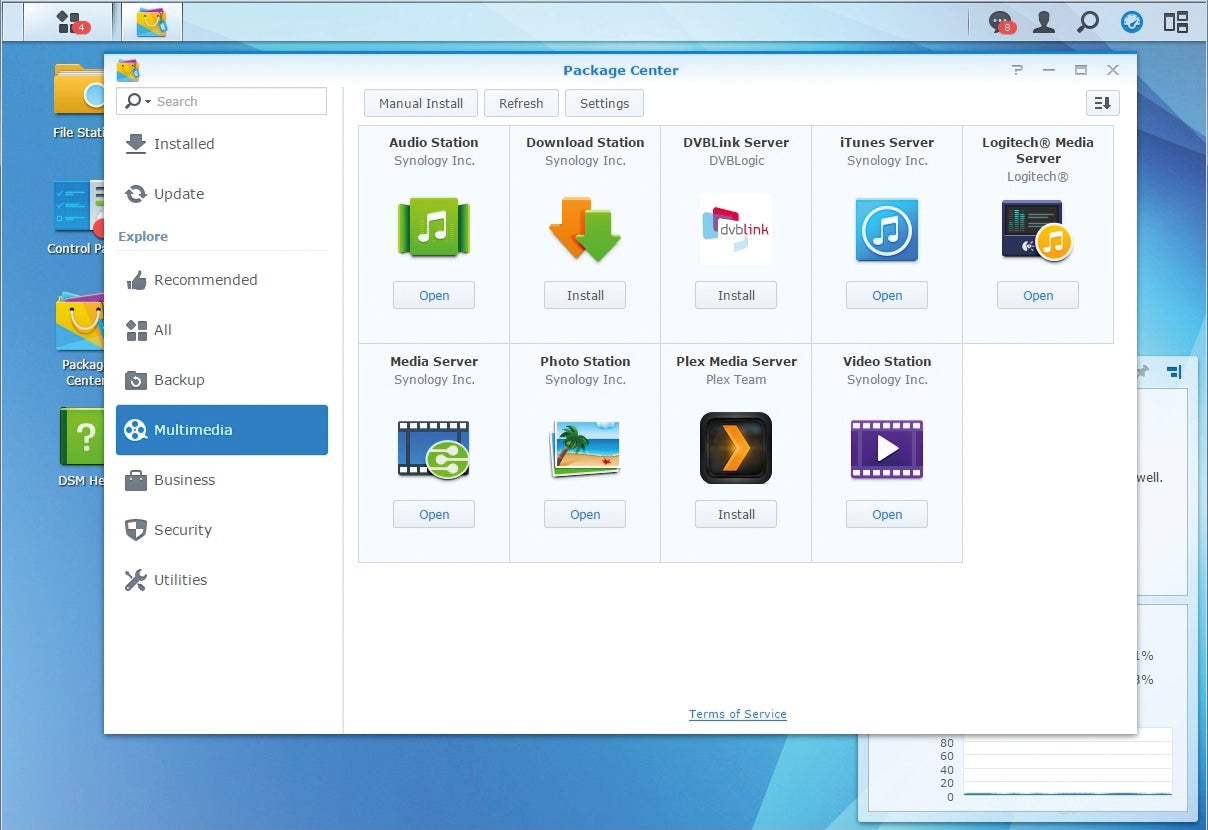
Logitech’s Squeezebox app might be called “Logitech Media Server” on your NAS
Once Squeezebox has scanned and created your music library, you’ll see the main Squeezebox web page. If you add music to your Squeezebox server in the future, you’ll have to click on the Settings button at the bottom-right and then click the Rescan button on the settings page that appears to make sure it’s added to the library.
The easiest way to use Squeezebox is to create playlists, but this is a little clunky. You have to browse your music library in the left-hand pane of Squeezebox and add tracks to the right-hand pane via the small ‘+’ icon that appears when you hover your mouse over an item in the left-hand pane. Once the right-hand pane is populated (you can move tracks up and down the order), you need to click the small Save button at the lower right corner and then name the playlist via the input box that will appear at the top of the left-hand pane. Network lag can lead to seconds passing after each mouse click, making the process even more annoying, so be patient. Thankfully you can add groups of tracks to playlists: if you browse by genre, album or artist in the left pane you’ll see that each result has the ‘+’ icon, so you can add all Blues tracks to a playlist with a single click, for example.
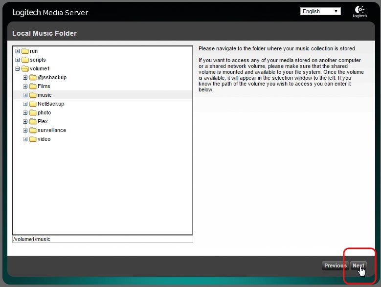
Just point Squeezebox at the Music folder of your NAS (or alternative media server) and it will create your music library automatically
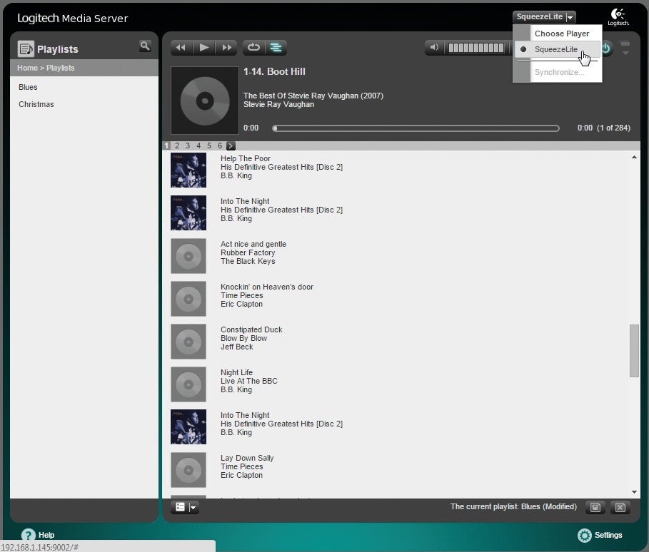
You may now have a Squeezebox server and music playlists, but you’ll need a Squeezebox player to actually listen to music (you can’t even listen to music via the Squeezebox web page, as it’s just a remote control). Below we show you how to make your Pi into a Squeezebox player, but for now we’ll use an iOS or Android device. Install Squeezecast (free, iOS) or SB Player (£2.35, Android) on your smartphone or tablet.
You’ll need to enter the settings for your Squeezebox server. You can find the IP address and port by looking at the address of the Squeezebox web page; ours said ‘192.168.1.145:9002’ so our server had an IP address of 192.168.1.145 and Squeezebox was using port 9002. The app should then find your Squeezebox server and load your playlists and tracks. The Squeezebox web page should also report that it’s found a Squeezebox player in the drop-down menu toward the top-right of the page; in the case of iOS’s Squeezecast, the device and app showed up as ‘Squeezeslave’.
Setting up your Raspberry Pi
Using a mobile device is a useful way to test that the back end of your setup is working. The next steps show you how to play your music via your Raspberry Pi.
We’re now going to configure the software on the Raspberry Pi that turns it into a Squeezebox Player, capable of receiving and playing audio from the Squeezebox app running on your Squeezebox server. Configuring this software is tricky, but we’ve got a trick to ensure that you need to do it only once.
Before that, we need to transform the Pi into a Squeezebox player, and the first step is to increase the output volume of the Pi. Type ‘sudo alsamixer’ and you should see a curious ASCII volume control (pictured below). Check that Alsamixer has recognised your sound card by looking at the information in the top-left of the screen. It will probably say ‘bcm2835 ALSA’ (or bcm2836 for the new Pi 2), which is the Pi’s built-in audio.
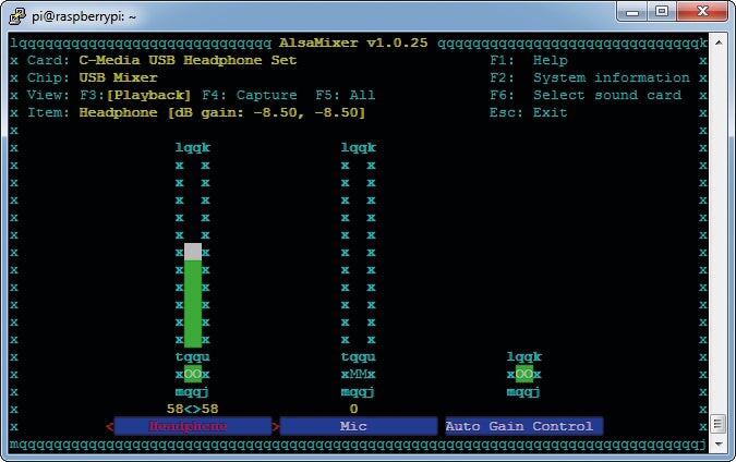
Use Alsamixer to adjust your Raspberry Pi’s audio input and output levels
To change this to the USB sound card we decided to use for this project (see Part 1), press F6 and use the down arrow to highlight the C-Media option, then hit Enter. As our USB sound card has both a stereo output and a microphone input, it has two levels. Alsamixer should highlight the Headphone level by default (the blue bar will have red text and red arrow brackets) so you need only press the up arrow until the level bar is at 100. Oddly, you then have to exit Alsamixer (press Escape) and only then save the change you’ve made. Type ‘sudo alsactl store’ and hit Enter.
Your next job is to install a few audio libraries so that all the files – no matter what their format – can be played by the Pi. Type ‘sudo apt-get install libfaad2 libflac-dev libmad0’ (without the quotes) and hit Enter. You’ll have to agree to download and install at least one of these libraries – type ‘y’ and press Enter when asked.
Set up Squeezelite
Squeezelite is an open-source project that can turn a Linux computer into a Squeezebox player, and it comes in different flavours depending on the hardware you wish to run it on; you’ll need the ‘armv6hf’ version. You’ll have to download the file to the temporary folder of your Pi, then move this file to the /usr/bin folder. After this you’ll need to change to the /usr/bin folder, and make the file you downloaded executable. To perform all these steps, type the following lines into your Pi’s console:
cd /tmp
wget http://squeezelite-downloads.googlecode.com/git/squeezelite-armv6hf
sudo mv squeezelite-armv6hf /usr/bin
cd /usr/bin
sudo chmod a+x squeezelite-armv6hf
Now you should test that Squeezelite works, but you’ll need two pieces of information: the code for your USB sound card and the IP address of the Squeezelite server. You can find the USB sound card’s code with the command sudo ./squeezelite-armv6hf –l. A load of options will appear on your screen, and you need to find an entry for the C-Media Front output. In our case the code for this output is ‘front:CARD=Set,DEV=0’. You can find the IP address of the Squeezebox server by either logging into your router or loading the server’s web page in a browser (we set a static IP address for this server in last month’s guide, which was 192.168.1.145.) Now you can give Squeezelite a spin:
./squeezelite-armv6hf -o
front:CARD=Set,DEV=0 -s 192.168.1.145
Replacing the IP address at the end with your Squeezebox server’s IP. Oddly, if everything is working, the Pi should look as though it’s crashed, as it won’t give you a new command prompt. Don’t panic, as this means that Squeezelite is running.
If Squeezelite launches properly, it will probably look as though your Pi is broken, but check the Squeezebox web page and you’ll see that everything is running fine
You can check this is the case by opening Squeezebox’s web page; you should see ‘Squeezelite’ listed in the ‘players’ drop-down menu at the top-right of the page. Play a track via the Squeezebox web page and it should start playing through the speakers plugged into the USB sound card of your Pi. If not, check your speakers and their connection with the USB sound card (we found we had to rotate the speakers’ mini-jack connection within the USB sound card’s headphone port to make a reliable connection).
Running Squeezelite on startup
The next step is to ensure Squeezelite runs on startup. To do this you should use a script created by a Dutch VW enthusiast called Gerrelt. Press Ctrl-Z to end Squeezelite and your Pi should present its command prompt again. You’ll need to download a script file, so change to the temp folder again, download the script, move it, go to its new location and make it executable, just as you did with the original Squeezelite file:
cd /tmp
sudo wget http://www.gerrelt.nl/RaspberryPi/squeezelitehf.sh
sudo mv squeezelitehf.sh /etc/init.d/squeezelite
cd /etc/init.d
sudo chmod a+x squeezelite
sudo update-rc.d squeezelite defaults
The last command tells the Pi there’s an executable script to run during startup; the ‘update-rc.d’ command is linked to the /etc/init.d folder, which contains items to be loaded during the bootup sequence. However, although you’ve ensured that Squeezelite launches every time the Pi boots up, Gerrelt’s script can’t automatically set the correct settings for your Pi or network, so you’ll have to edit the script, by typing ‘sudo nano squeezelite.’
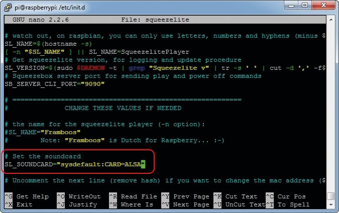
Hunt through Gerrelt’s amazing Squeezelite script for the few options you need to tweak
In the script, the first option to check is that Squeezelite (on your Pi) knows which port your Squeezebox server is using. Find the entry for SB_SERVER_CLI_PORT. Gerrelt’s default port is 9090, but the web page of our Squeezebox server says the port is 9002, so we needed to change the value.
The default sound card is the Pi’s integrated model, so find the entry for ‘SL_SOUND CARD’ and change the entry from “sysdefault:CARD=ALSA” to “front:CARD=Set,DEV=0” (or whatever code your USB sound card uses). Note once again that you’re declaring the sound card as a variable, so you need to include those double-quotes.
Quality control
For better audio quality, Gerrelt recommends you enable the ‘SL_ALSA_PARAMS=”80″‘ entry that increases the size of Squeezelite’s output buffer. It’s commented out by default, so you need only remove the hash symbol. This option can be tricky to find, so press Ctrl-W (to search), type ‘params’ and hit Enter; the option should be highlighted. To save and exit, press Crtl-X, Y and then Enter.
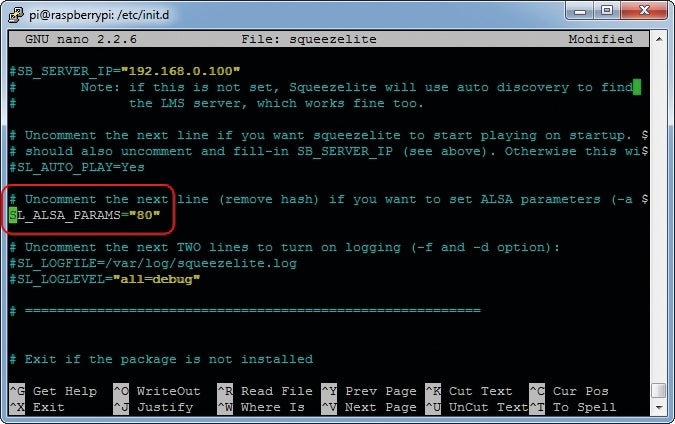
A simple script tweak can improve audio quality
You can test Gerrelt’s script by typing ‘sudo ./squeezelite start’ and pressing Enter. This is a much more elegant way to start a service on a Pi than the quick and dirty method we used earlier: the Pi will report the settings Squeezelite has used and even give you a command prompt so you can continue to work. You can check that Squeezelite is working by logging into your Squeezebox server and opening the Squeezebox player menu (in the top-right). Instead of the player being called ‘Squeezeslave’ it should now be called ‘raspberrypi’. That’s because Gerrelt’s clever script reports the name of the Pi to the Squeezebox server. Perform a final check by typing ‘sudo reboot’ and hitting Enter. The Pi should reboot and, once it has done so, your Squeezebox server should again see a Squeezebox player called ‘raspberrypi’.
Finally, Gerrelt recommends setting an automatic reboot each night (to clear some gremlin that can interfere with Squeezelite). Edit the crontab (which sets automated routines) by typing ‘sudo crontab –e’ and hitting Enter. On a new line at the end of the file, add ‘0 3 * * * sudo /sbin/shutdown –r now’ (without the quotes, but pay attention to the spaces) to reboot the Pi at 3am every day. Then save and exit by typing Ctrl-X, Y and then Enter.
Clone yours
We promised that you wouldn’t have to go through the same setup process for every multiroom audio speaker you wish to create, and here’s how. Power down your Pi (sudo shutdown –h now) and unplug it. Take out the microSD card, put it back in your PC and fire up Win32 Disk Imager, the tool you used to write Raspbian on to the card in part 1. You’ll need to cheat the software a little by selecting a file in a memorable location on your hard disk – perhaps the original Raspbian image.
Then edit the name in the Image File field from ‘…/2014-09-09’wheezy-raspbian.img’ to something like ‘…/audiopi.img’ and click the Read button (don’t click Write at any point during this process). Win32 Disk Imager will make a 1:1 clone of your SD card, so if you used an 8GB card (as we did) the resulting image will be 8GB; ensure your memorable location has sufficient space. You then use this image (and the Write button of Win32 Disk Image) when writing to the SD card of your other Pi-based wireless speaker units.
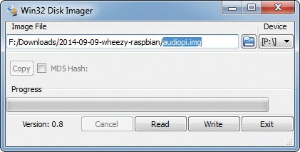
Use Win32 Disk Imager to clone your SD card. Type in a location and name for the clone file and press the ‘Read’ button
However, you’ll now have a bunch of speaker controller units all called ‘raspberrypi’. You’ll therefore need to change the name of each unit so you know where to send your music. Once a cloned Pi has booted up and you’ve logged on (with your updated password, remember), type ‘sudo raspi-config’ and hit Enter. Head to ‘8 Advanced Options’ and then ‘A2 Hostname’. Read the advice on the next screen and hit Enter to set a new host name for the Pi. This is the name that Gerrelt’s script reports to your Squeezebox server, so chose something like ‘Lroom1’ (remembering that if you use a character that’s not a letter, number or hyphen, the Pi will behave very oddly, just as the advice screen warns). Reboot and the updated host name should appear in the Squeezebox players menu of your Squeezebox server.
Make a Raspberry Pi smart doorbell
It might sound silly, but connecting your doorbell to the internet is a great idea. At a basic level, it means that whenever someone presses your doorbell, your smartphone or tablet will chime so you’ll never miss a delivery or visitor, whether you’re down the bottom of the garden or listening to loud music in your study. You’ll also be able to log doorbell presses, so you can prove that the courier you’ve waited for all day really did just stick the “sorry you were out” card through the letterbox without even trying the bell.
To connect your doorbell to your network (and the internet beyond), you’ll need a Raspberry Pi and a Class 4 (or faster) 4GB SD card with the latest version of Raspbian installed. You’ll also need a power supply and an internet connection for the Pi, as well as all the doorbell-specific hardware we’ve listed below.
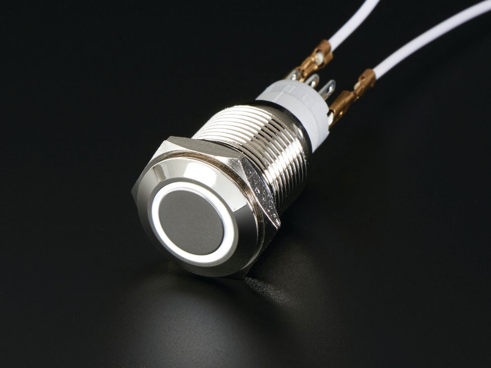
If you don’t want to buy the Adafruit doorbell we list, you can also use any waterproof, momentary-type push button as a doorbell. If you wish to use an alternative pushbutton – perhaps the one currently next to your door, or one that’s a little wider than the slightly skinny 16mm Adafruit button – ensure the button is a momentary button rather than an on/off switch button, and that its contact and insulation resistances are close enough to that of Adafruit’s button. A momentary button only sends a signal when it’s being pressed, while an on/off button switches from one state to another once pressed; use the wrong button and your doorbell will buzz until the next time someone presses the button.
What you need
*Raspberry Pi (plus power supply and 4GB, Class 4 SD card) with internet access
*PC speaker (standard active type with 3.5mm plug)
*Android or Apple smartphone
*Pushover account (see below)
*Adafruit Waterproof Metal Pushbutton with LED Ring
*10k-Ohm resistor
*Multicore cable (at least 4-strand, such as telephone wire)
*Soldering iron and solder
*Wire strippers
When ordering, why not support your local electronics shop? Below is a table of certified UK Adafruit suppliers. You may have to search for ‘momentary pushbutton’ or similar under the Adafruit section on these sites to find the correct button. Many of these suppliers will also be able to provide the resistor, probably as a pack of 20 for around £1, and the multi-core cable (telephone wire costs around 75p per metre).
| Certified UK Resellers | ||
| Name | Location | Website |
| 4Tronix | Sheffield | www.4tronix.co.uk |
| Cool Components | London | http://coolcomponents.co.uk |
| ModMyPi | London | www.modmypi.com |
| Oomlout | Leeds | http://oomlout.co.uk |
| Phenoptix | Nottingham | www.phenoptix.com |
| Pi Supply | Croydon | www.pi-supply.com |
| PKMC | London | http://pkmc.uk.com |
| Proto-Pic | Kirkcaldy | http://proto-pic.co.uk |
| SK Pang electronics | Braintree | www.skpang.co.uk |
| Tandy | Oxford | www.tandyonline.co.uk |
| The Pi Hut | Cambridge | http://thepihut.com |
Once you’ve installed Raspbian on your SD card connect the Pi to your network and power it up, then log in with the default user name of ‘pi’ and password ‘raspberry’. Then expand the file system via the blue configuration screen and reboot. Log in again and type ‘sudo apt-get update’ and hit Enter; once Raspbian has updated, update its applications by typing ‘sudo apt-get –y upgrade’.
Remember to expand the file system, otherwise your Pi won’t be able to access the entire storage capacity of your SD card
Next you need to convert the Pi’s GPIO (General-Purpose Input/Output) connection (the double line of bare pins near the SD card slot) from Serial mode to Software Access mode. To do this you need to edit a boot file. Type ‘sudo nano /boot/cmdline.txt’ and hit Enter. You’ll need to edit the current line:
dwc_otg.lpm_enable=0 console=ttyAMA0,115200 console=tty1 root=/dev/mmcblk0p2 rootfstype=ext4 elevator=deadline rootwait
To match this line:
dwc_otg.lpm_enable=0 console=tty1 root=/dev/mmcblk0p2 rootfstype=ext4 elevator=deadline rootwait
Press Ctrl+X, then Y, then Enter to close, save and overwrite the file with the new changes. Then edit another setup file by typing ‘sudo nano /etc/inittab’ and pressing Enter. Comment out the last line (so that it’s ignored) by inserting a hash at the start of the line, to match the example below, then exit and save the change as before.
#TO:23:respawn:/sbin/getty –L ttyAMA0 115200 vt100
You can now reboot your Pi by typing ‘sudo reboot’.
Install Pushover
The service we’ll use to send doorbell alerts to your smartphone is called Pushover and is available for Apple’s iOS and Google’s Android but not Windows Phone. The Android version has a five-day free trial before asking for $4.99 as an in-app purchase, while the iOS version is £2.99. Pushover can push any kind of alert to your smartphone, so can be used for more than just your doorbell. Install the app, sign up for an account and name the device which you want to receive the notifications. If asked, you’ll obviously want to give permission to Pushover to send you Push Notifications. A welcome message should appear on the Pushover Home screen, telling you that the device can receive messages.
Next, head to https://pushover.net and log in. You’ll be asked to verify your email address, do so and then click Register an Application under the Your Applications section. You’ll be asked to give this new application a name, type, description, URL and icon – see the screenshot for our suggestions. Click Create Application and note the API Token/Key that Pushover generates (it’s a long string of numbers and letters that’s case-sensitive) before pressing Save Changes. Pressing this button will take you to a usage screen with two graphs, but just head home by clicking the Pushover logo at the top-left of the screen. From this main screen, note your user key (the top-most of the two long strings of letters and numbers) and log out.
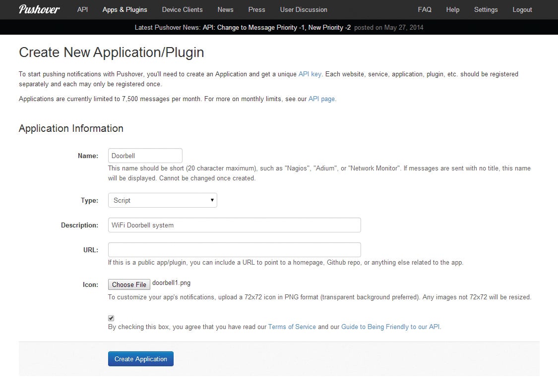
Create a New Application in Pushover for your doorbell
Back on your Pi, install the audio player mpg321 by typing ‘sudo apt-get install –y mpg321’ and pressing Enter. You’ll then need to save an MP3 audio file to your Pi that will act as your doorbell chime. We chose one from Soundjay, a royalty-free site with a choice of seven sounds. To download an MP3 (we chose file 1, for example) from this site directly to your Pi, type ‘wget http://www.soundjay.com/door/doorbell-1.mp3’ and the download should start. You’ll also need to install the GPIO add-on for the Python programming language, by first installing the Python development toolkit, and then the GPIO add-on:
sudo apt-get install –y python-dev
sudo apt-get install –y python-rpi.gpio
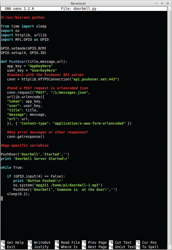
The code that drives your WiFi Doorbell, using the Python programming language
Create a new Python script by typing ‘sudo nano doorbell.py’ and then copy the Python doorbell code, inserting your user and application keys instead of the phrases ‘AppKeyHere’ and ‘UserKeyHere’. You could also download the example script from our server by typing ‘wget www.shopperdownload.co.uk/adproj/doorbell.py and edit it with nano, as above. Save and exit by pressing Ctrl+X, Y, then Enter. You can now shut down the Pi by typing ‘sudo shutdown –h now’ and pressing Enter. Wait 15 seconds or so until the Pi is powered down, and disconnect the power, SD card and Ethernet cable.
Soldering the wires
Strip the outer sheath from the multi-core cable, and then strip the ends from four of the wires. Our phone cable had six wires inside, so we snipped the green pair off altogether. On the Adafruit Pushbutton there are five connections, labelled +, -, NC1, NO1 and C1. It doesn’t matter which wire you use for which connection, but write down which colour you’ve connected where. For example, we used the Orange with White wire for positive, White with Orange for negative, Blue with White for NO1 and White with Blue for C1. Solder the wires to the Pushbutton’s connections. If you’re nervous about soldering, you can connect everything dry by curling the bare wire around your pins and connections with a pair of needle-nosed pliers.
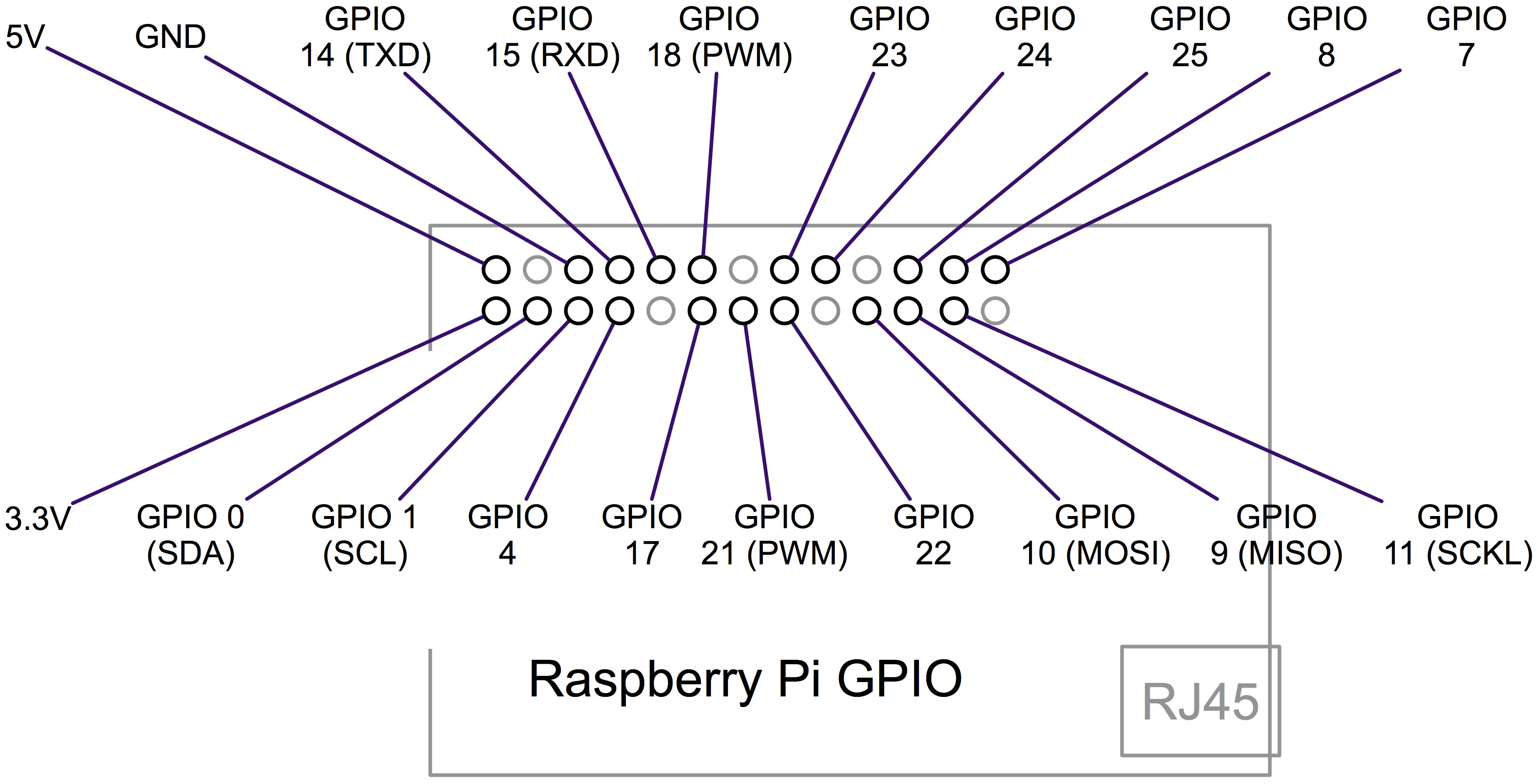
This image shows the function of each of the 26 pins of a Pi’s GPIO connector. Pin 1 is marked on the Pi (as P1). When wiring, orientate the Pi so the GPIO connector is at the top-left corner of the circuit board for easy reading
Next, find your 10k-Ohm resistor. This will have bands of brown then black (to make 10), followed by orange (x1k), then gold (tolerance of five per cent). You need to place the resistor between the 3.3V pin on the GPIO and the GPIO pin you intend to use for control – we’ve used Pin 4, which corresponds to GPIO 4 (used in the Python code above). Then connect the NO1 wire from the Pushbutton (Blue with White, in our case) to the GPIO 4 side of the resistor (or whichever pin you have used). The other connections are straightforward: C1 goes to GND (Ground) on the GPIO, as does –, while + goes to the 5V GPIO pin. The spec sheet of the Pushbutton says that its LED requires 6V, but we found the 5V supply from the Pi was perfectly fine.

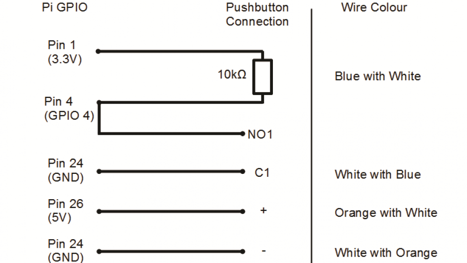
Use these diagrams to help you wire your Pushbutton to your Pi
Ensure that no bare wire touches any other bare wire (unless they share a GPIO pin), and once you’re happy, reassemble and power up your Pi. Log in and you’re ready to activate the doorbell script. Type ‘sudo python doorbell.py’ and you’ll see the ‘Doorbell Server Started’ message on the Pi’s screen, followed a few seconds later by your phone buzzing with the Pushover alert ‘Doorbell: Started’. Now press the Pushbutton and you should hear the MP3 chime you downloaded followed quickly by a Pushover alert telling you ‘Someone is at the door!’
To start the Doorbell.py script automatically, we’ll add it to the crontab. Type ‘sudo crontab –e’ to open the crontab file. Then instert the line ‘@reboot python /home/pi/doorbell.py &’ on its own line at the end of the crontab file, then save and exit. Test whether the script launches automatically by typing sudo reboot; after 30 seconds or so, you should receive the ‘Doorbell: Started’ message on your phone.
Make it wireless

Having to route an Ethernet cable to your front door is a pain, so why not make the Pi controlling your doorbell wireless? There are a few Wi-Fi dongles compatible with the Pi; the most common being the Edimax EW-7811Un, which costs £8 from Dabs. The driver for this dongle is already installed with Raspbian, so it’ll work as soon as you plug the dongle in.
Overkill?
Using a Pi to make a wireless doorbell might seem like overkill when you can get wireless doorbell kits for under a tenner, but there’s a lot more you can do when a Pi powers your doorbell. Without adding any more code, for example, your Wi-Fi Doorbell can send your phone Pushover alerts over any kind of data connection, so you don’t even have to be in range of your home’s Wi-Fi. This means you can rush back from the shops to meet Great Aunt Ethel who was meant to call at half-past, not quarter-to. You might also be able to prove that your pesky courier didn’t in fact call earlier by showing the company the Pushover graph for your application.
Make a video intercom system
On the previous page we showed you how to receive real-time alerts on your smartphone when someone presses your doorbell. Although you may be satisfied with your Wi-Fi doorbell and the satisfaction of never missing a caller at your door again, we promised you more, such as photos of callers and a live video stream of who’s at your front door. As we’ll show you, this is possible with a Raspberry Pi and a bit of tinkering.
It’s possible to use the Pushover service, which we used to send alerts from your Raspberry Pi to your smartphone, to log how many times your doorbell has been pressed. However, the logs only take the form of how many alerts per day have been sent. This clearly won’t be enough to convince a courier company’s customer complaints department that they were to blame for the failed delivery, rather than you. If your complaint is more serious than a failed delivery – perhaps troublesome youths are pranking you with frequent games of Cherry Knocking, for example – you’ll want more than a text file to prove guilt.
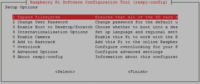
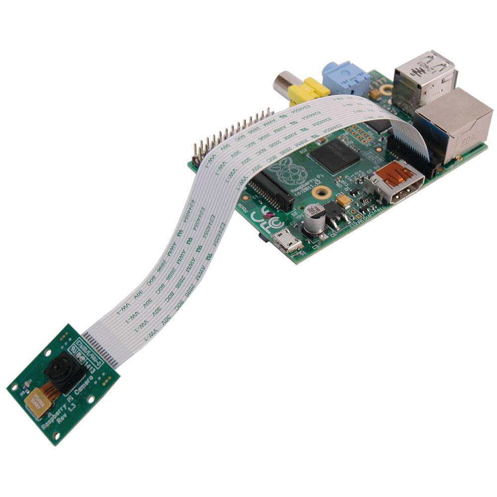
What you need is incontrovertible evidence that someone approached your door with untoward intentions, and that’s best done with a video. It’s best to use the Raspberry Pi’s bespoke Camera Module (£20.15), as this can use the Pi’s graphics processing unit and so leave the main processing unit with some headroom for other tasks. We’ve previously discussed how to connect the Camera Module’s strange ribbon cable to the Pi, but the Raspberry Pi Foundation’s video is a clear guide. Once the camera is plugged in securely and the Pi has booted up, you’ll need to activate the camera by launching the Pi Console (type ‘sudo raspi-config’) and selecting the Enable Camera option (use the arrow keys on your keyboard to navigate the menu). Once the camera is enabled, select Finish and agree to reboot.
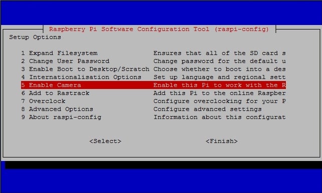
Don’t forget to enable the Camera Module before you do anything else with your Pi
Update Raspbian with the ‘sudo apt-get update’ command, and then update your applications with ‘sudo apt-get –y upgrade’. You should now be able to test the camera. Type ‘raspistill –v –o test.jpg’ and you’ll see the right LED on the Camera Module itself light up and a load of photography-related information appear on your screen. You can double-check the camera is working by typing ‘ls’ to list the contents of the folder you’re currently looking at – you should see a file called test.jpg.
If you haven’t before, now is the time to set a fixed IP address for your Pi. This is best done by assigning the Pi its own IP address from your router’s setup pages. You’ll need to reboot your Pi for it to pick up its new, fixed IP address, so type ‘sudo reboot’.
Your call may be recorded
An easy way to integrate the Camera Module into your doorbell system would be to modify the Python script that monitors your doorbell and sends the Pushover notification to your phone, so that it also takes a picture, possibly with a file name that contains the current date and time. Doing so is slightly tricky, as the Pushover script is based on Python rather than the more basic Bash. First, we needed to install the Python version of picamera: ‘sudo apt-get install –y python-picamera’. It could well be that this is installed already, but it’s best to check.
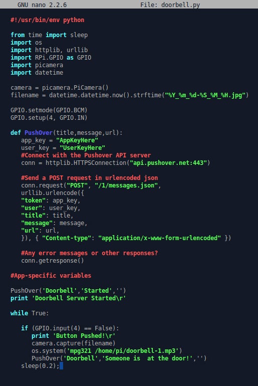
Add a few lines of code, and your doorbell can automatically take a photo or video of your caller, as well as buzz your phone
After this, edit your doorbell.py file (‘sudo nano doorbell.py’) and enter the following lines at specific points in the script, to keep the code tidy. Under the four ‘import’ lines add:
import picamera
import datetime
camera = picamera.PiCamera()
filename = datetime.datetime.now().strftime(“%Y_%m_%d-%S_%M_%H.jpg”)
The hard return space between these groups isn’t entirely necessary, but it keeps things neat. The first two lines import some dependencies: the Python library for the Camera Module and the datetime module, which will let us name pictures taken by the camera according to the current time and date.
Next, navigate to the section of code toward the end, after the ‘if’ statement. Add the line ‘camera.capture(filename)’ on its own line and then save and exit. Every time someone presses your doorbell, your Pi will take a picture and save the image named according to the time and date. You could also take a 10-second video by using the following code instead of the ‘camera.capture’ line:
camera.start_recording(filename)
sleep(10)
camera.stop_recording()
To do the job properly you’ll want a video that starts recording as soon as someone comes into view of your front door, however, and not just when someone has pressed the bell. We used such an application in Advanced Projects, Shopper 315, where we used a Raspberry Pi to make a CCTV system – the application is called Motion. More precisely, we used the version of Motion ported to run on the Pi by dozencrows of the Raspberry Pi forum, which he or she has called motion-mmal. Installing motion-mmal is fairly convoluted, so refer to the smart doorbell guide on the previous page of this article.
Unfortunately, you won’t be able to take still photos with the code above at the same time as record video with the applications below. This is because whichever application – photo or video – gets hold of the camera first during Pi bootup will refuse to share the camera with anything else.
We had a little trouble getting motion-mmal to start automatically when the Pi reboots, probably due to an update for Raspbian. Therefore, instead of editing its daemon behaviour (with the command ‘sudo nano /etc/default/motion’) we added motion-mmal as a cronjob by adding the line ‘@reboot motion’ to the end of the file. Access the cron tab by typing ‘sudo crontab –e’; the process for adding the cronjob is the same as we covered previously. You might also want to check some of the settings in motion-mmal’s config file.
Motion-mmal can also provide a live video stream, allowing you to see who’s at your door in real-time: see someone with a clipboard and you’ll probably just get on with the weeding, for example. However, only certain smartphone browsers understand motion-mmal’s live video feed; Chrome hasn’t got a clue, Maxthon crashes, Opera Mobile ignores you, Dolphin tries to download the video stream and UC Browser just gives you a page of raw code. The only mobile browsers we found to work were Safari and Firefox. If you’re lucky enough to use either of those as your default browser, then you can just use motion-mmal to provide the live stream and thus turn your phone into a CCTV monitor.

Create a video stream via motion-mmal and you can see who’s at your door in Firefox or (as here) Safari
Who’s at the door?
If you don’t use Safari or Firefox as your main web browser on your phone, and don’t wish to switch, you’ll have a dilemma: either you can record motion-activated videos using vi motion-mmal, or you can use MJPG Streamer to send live video to your phone. If you choose the latter, don’t install motion-mmal and instead use jacksonliam’s experimental version of MJPG Streamer. This project integrates support for the Pi’s Camera Module, making for a much easier install process. We thank Miguel Mota for bringing this project to our attention. Type the following commands into your Pi.
sudo apt-get install -y libjpeg62-dev cmake
git clone https://github.com/jacksonliam/mjpg-streamer.git ~/mjpg-streamer
cd ~/mjpg-streamer/mjpg-streamer-experimental
make clean all
sudo rm -rf /opt/mjpg-streamer
sudo mv ~/mjpg-streamer/mjpg-streamer-experimental /opt/mjpg-streamer
sudo rm -rf ~/mjpg-streamer
LD_LIBRARY_PATH=/opt/mjpg-streamer/ /opt/mjpg-streamer/mjpg_streamer -i “input_raspicam.so -fps 15 -q 50 -x 640 -y 480” -o “output_http.so -p 9000 -w /opt/mjpg-streamer/www” &
The first line installs a couple of dependencies, while the second connects you to the project’s ‘respository’ (the collection of project-wide source code) on GitHub (an online library of repositories). The rest of the commands follow jacksonliam’s instructions for setting up his software, while the last line actually executes MJPG Streamer.
If you cast your mind back to our first look at the Camera Module, you’ll find some of the commands in that last line familiar. The letters preceded with dashes are called switches, and describe a certain parameter or setting for the main command ‘input_raspicam.so’. For example, ‘-fps 15’ sets the frame rate of the video at 15fps, ‘-q 50’ sets the quality to 50 per cent, and so on. We’ve played with these values – particularly lowering the quality value to increase the resolution – but couldn’t see much difference in the final video so in the end left them at their defaults. To see for yourself, open a web browser on any device on your network and point it toward your Pi’s IP address followed by ‘:9000’ (as specified by the ‘-p’ port switch). In our example we’d type in 192.168.1.100:9000. Usually the Stream tab is fine, but on some browsers you might have to use the JavaScript or other tabs to see the video.
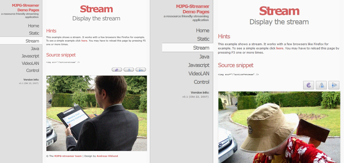
Use MJPG Streamer to provide the live video stream, and you can view it in any browser you wish. We doubt you’d want to open the door to either of these callers
However, we want the video stream to start automatically whenever the Pi is powered up, so we’re going to write a quick Bash script. First, though, you need to stop MJPG Streamer. Find its process ID (PID) by typing ‘pgrep mjpg_streamer’; your Pi will return a four-digit number, so type ‘kill pid XXXX’, replacing the Xs with that number. We want the Bash script to be created somewhere easily accessed, so type ‘cd’ to go back to the /home/pi folder, and then ‘sudo nano streamer.sh’ to create a Bash script called streamer.sh and open it in a text editor. Enter the following before saving and exiting.
#!/bin/bash
if pgrep mjpg_streamer > /dev/null
then
echo “MJPG Streamer is already running”
else
LD_LIBRARY_PATH=/opt/mjpg-streamer/ /opt/mjpg-streamer/mjpg_streamer -i “input_raspicam.so -fps 15 -q 50 -x 640 -y 480” -o “output_http.so -p 9000 -w /opt/mjpg-streamer/www” &
echo “MJPG Streamer is not running”
fi
Make this script executable by typing ‘sudo chmod ugo+x streamer.sh’ and then add the script to the crontab; type ‘sudo crontab –e’, then add to the end of the file ‘sudo bash /home/pi/streamer.sh’ and save and exit. Reboot your Pi to check that the Pushover service works and the video stream starts automatically.
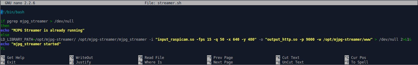
Knock together a quick Bash script to automate the live video stream neatly
Linking up and limitations
To finish the job, whether you use motion-mmal or MJPG Streamer, you need to add the URL of your video feed to your Pushover alert. Edit the doorbell script by typing ‘sudo nano doorbell.py’ and scroll to the bottom to find the alert text. Then enter the URL of the video stream you want to access. In our example, where our Raspberry Pi’s IP address is 192.168.1.100, if the stream is from motion-mmal we’d enter http://192.168.1.100:8081, and if it’s from MJPG Streamer we’d enter http://192.168.1.100:9000/stream. Save and exit, reboot and you’re all set.
While we expect some limitations on a computer costing £27, having to choose between recording video or seeing live video does rankle, as the capability to do both is clearly there in the Pi. We got our hopes up when we saw silvanmelchior’s RPi_Cam_Web_Interface, which not only streams live video to any browser (using Motion, no less) but presents lots of camera settings in a very friendly way. However, despite our best efforts, we couldn’t get Silvan’s project to work. Similarly, we had hoped to be able to talk to our doorbell via our smartphone – our voice would be played through the same speakers that play the doorbell chime, so we could ask the caller to be patient, or to come and find us in the garden. Unfortunately we couldn’t get this to work as the required Android and iOS apps weren’t compatible with the Pi. If you want to talk to your doorbell, or even the person standing near to it, you’ll either have to shout like the rest of us, or delve into Raspberry Pi-based VoIP applications. And that’s a topic for another day.
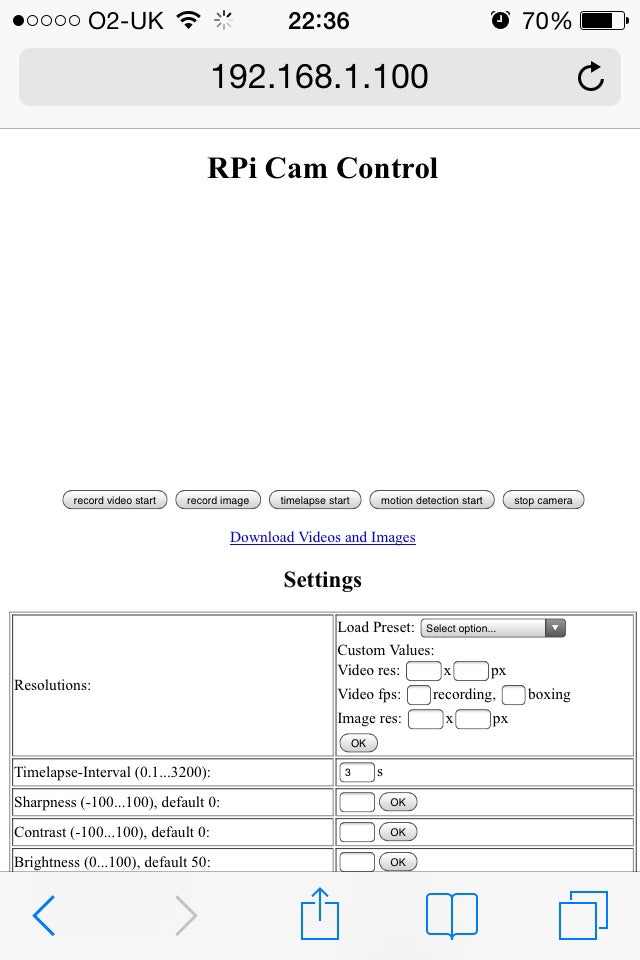
The RPI_Cam_Web_Interface is exactly what we wanted from our doorbell-based live video streaming service, but we couldn’t get it to work reliably
Make a Raspberry Pi CCTV security system
There’s no need to spend a fortune on a fancy security camera system to keep your home or business safe. We’ll show you how to put together a surveillance system for less than £50 and still get the same high-quality footage and extra features. All you need is a Raspberry Pi and a cheap camera. You can see an example of footage captured by our PiCam here.
To start you’ll need a Raspberry Pi (around £28), a Raspberry Pi Camera Module (£20) and a fresh install of the latest version of Raspbian (either download it or select Raspbian via the NOOBS software that’s pre-installed on the SD card of many Raspberry Pi kits these days). Check out this video guide if you’re not sure how to attach the fiddly camera module to your Pi. If you’re not using NOOBS, use SD Formatter 4.0 to prepare the SD card, and Win32 Disk Imager to flash the downloaded Raspbian ISO file onto the SD card. Once the Raspbian operating system is installed, insert the SD card into the Pi’s card reader and power it up; you should select Expand the File System and Enable the Camera from the blue menu that appears, before restarting the system.
Once all the setup text has stopped scrolling down your screen, log in using the default user name and password of pi and raspberry. As is best practice, update the OS and its pre-installed applications by typing ‘sudo apt-get update’ and then ‘sudo apt-get –y upgrade’. Sharp-eyed readers will notice that the syntax for the second job has changed subtly since we last talked about setting up Raspbian – such is Linux, which is why Linux administrators try not to update installations once they get everything working satisfactorily.
Before installing the software that will handle the motion detection and recording, the final preparation is to ensure that your Pi is running the latest firmware version. Type ‘sudo apt-get install rpi-update’ and then ‘sudo rpi-update’. It’ll take a while for the new firmware to install, but once done you need to reboot the Pi by typing ‘sudo reboot’.
Remote control
Because having a CCTV camera with a keyboard and HDMI screen hanging off it is wildly impractical, we want to start accessing and controlling the Pi remotely as soon as it’s been successfully updated. This is possible via SSH (short for Secure SHell protocol), which is installed by default with Raspbian. To make SSH run every time the Pi starts up, type ‘sudo update-rc.d ssh defaults’.
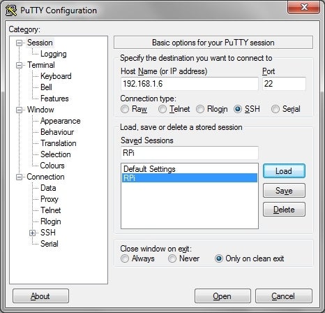
Use PuTTY to remotely control your Pi from another PC
To access the Pi remotely from a Windows PC, you need to download an SSH client – we used PuTTY. Download PuTTY from the putty.exe link. Once the .exe. file has downloaded to your Windows PC, place it somewhere convenient, such as on your desktop. When you launch it, you might feel overwhelmed by the options on offer, but all you have to do is enter the IP address of your Pi into the Host Name (or IP address) field and click Open. To save time later, you might want to click Save first and give the connection a relevant name – we’ve chosen RPi. You can find the Pi’s IP address by either finding it in your router’s management web page (you might also like to ask the router to assign the Pi a static IP address while there, if the option is available) or else type ‘ip addr show’ into the Pi. Once you have the IP address you’ll be able to log in to the Pi via PuTTY with the default pi and raspberry user name and password, and once you have remote control of the Pi you can unplug its keyboard and screen.
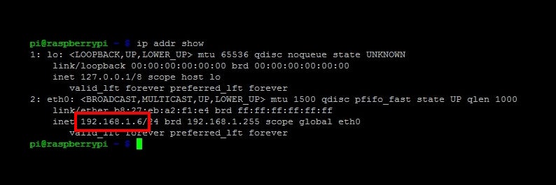
Find the IP address of your Pi by typing ‘ip addr show’; the IP address is highlighted in the screenshot
In motion
Now that you can access and control your Pi from the comfort of your main PC or laptop, we can really get to work on making a CCTV camera – from here on in, we’ll do everything via PuTTY. The software that’ll do all the heavy lifting in this project is called Motion. Install Motion in the usual way with ‘sudo apt-get install –y motion’.
However, Motion hasn’t yet been updated to work with the Raspberry Pi Camera Module, so we have to install a few hacks and workarounds – our thanks to dozencrows of the Raspberry Pi forum for doing much of the legwork. You need to type the following into the Pi’s terminal, pressing Enter after every instruction:
cd /tmp
sudo apt-get install -y libjpeg62 libjpeg62-dev libavformat53 libavformat-dev libavcodec53 libavcodec-dev libavutil51 libavutil-dev libc6-dev zlib1g-dev libmysqlclient18 libmysqlclient-dev libpq5 libpq-dev
wget https://www.dropbox.com/s/xdfcxm5hu71s97d/motion-mmal.tar.gz
tar zxvf motion-mmal.tar.gz
sudo mv motion /usr/bin/motion
sudo mv motion-mmalcom.conf /etc/motion.conf
To explain what that all does, the first line moves you to the temporary /tmp folder – a good place to download temporary files to, as the folder gets emptied every time the Pi starts. The next line is horrible, but is a belt-and-braces approach to ensuring the Pi has all the correct video libraries and codecs; some people have reported that merely libjpeg62 (type ‘sudo apt-get install –y libjpeg62′) is sufficient, so you might want to try that first and revert to our lengthy install line should that fail. The next line, wget…, fetches dozencrows’ tweaked files for Motion and the line after unpacks the .tar file (a .tar file is similar to a .zip or .rar file, in that it can contain multiple files). Then the two ‘sudo…’ lines move the two unpacked files from the .tar file into the appropriate places.
All the above should mean that the Motion software will now run on your Pi, but you need to edit Motion to tell it to run every time the Pi boots. Type, ‘sudo nano /etc/default/motion’ to edit Motion’s startup behaviour, changing the appropriate setting to ‘start_motion_daemon=yes’ (the term ‘daemon’ is Linux-speak for ‘service’.
Unfortunately, you’re not quite done yet, as you need to set the correct permissions for Motion to automatically create files, save files and generally be of any use. Again, we’ve gone for the belt-and-braces approach, as hopefully this will mean that this guide works even if Raspbian gets updated between the time of writing and whenever you have a spare couple of hours to follow it.
sudo chmod 664 /etc/motion.conf
sudo chmod 775 /usr/bin/motion
sudo touch /tmp/motion.log
sudo chmod 775 /tmp/motion.log
cd /home/pi
mkdir motion
sudo su
chmod 777 motion
Again, this isn’t a script, just single instructions typed into the command prompt, followed by Enter after each line. The first four lines set some basic permissions, the next two lines create a folder called motion in the /home/pi folder, which is the one you usually view and use. The penultimate line gives you Super User rights and the last line means that Motion can save files in the folder /home/pi/motion.
The last stage in setting up Motion – at least in a basic state – is to edit a few settings in its configuration file. Type ‘nano /etc/motion.conf’ to edit the file using the Nano text editor and navigate to the logfile setting. You can do this quickly by using Nano’s search function; type Ctrl+W, type ‘logfile’ and press Enter. Change the entry to read ‘logfile /home/pi/motion.log’. Then find ‘target_dir’ in the same way and change the destination folder to also be /home/pi/motion. Lastly, find ‘stream_localhost’ and set that to ‘off’.
For other recommended settings, and pointers to more specialised options, see the Motion.conf section at the end of this guide. For the moment, we’re only going to ensure that Motion is working, so hit Ctrl+X, then Y to save the changes you’ve made, followed by return to keep the file’s name.
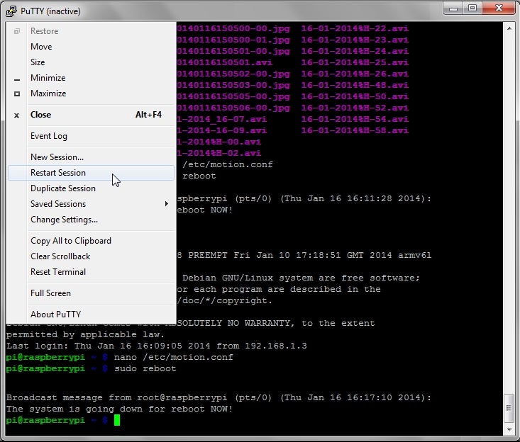
If you have to reboot the Pi, you’ll have to restart your PuTTY session (once the Pi has fully booted) and re-enter the username and password
Now that Motion will output to its own folder (/home/pi/motion) and will live-stream what the camera sees (via the stream_localhost setting) we can reboot the Pi and check Motion is running properly. Type ‘sudo reboot’ and while you’re waiting, download the Firefox web browser to your PC and install it without allowing it to become your main browser, unless you wish to switch. Once the Pi has rebooted, you should be able to enter its IP address followed by the port number of the stream_port setting (in our case, 192.168.1.6:8081, as port 8081 is the default) into the address bar of Firefox and see a live stream from the camera; unfortunately Chrome and Internet Explorer cannot handle this feed.
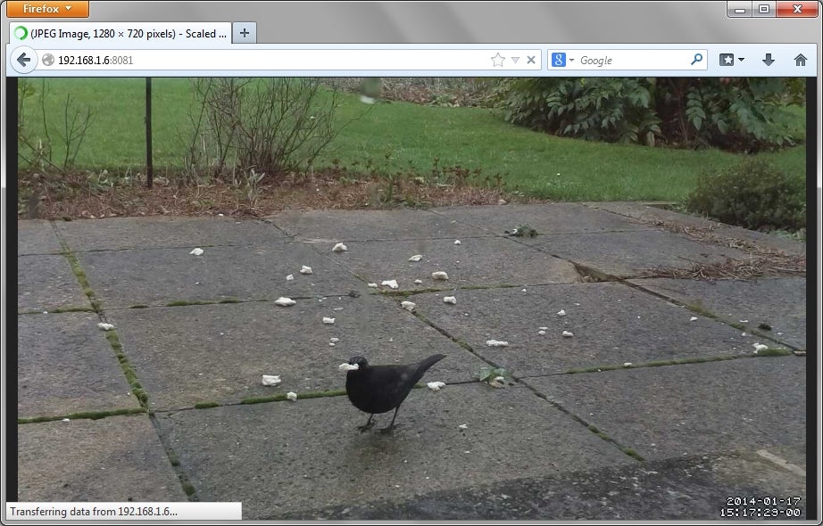
You can see a live stream from the Pi’s camera by using the Firefox web browser – just enter the IP address and stream port into the navigation bar
Another test to ensure that Motion is working is to look at the Camera Module – the red LED should light up very soon after the Pi boots. Now that the camera has seen some motion (your face, as you checked the red LED) you can log back into the Pi via PuTTY and check to see whether it’s saved anything in the home/pi/motion folder. Type ‘cd motion’ to enter the motion folder, and then ‘ls’ to list its contents. You should see a load of images and a video file. If not, check the motion.log file in the same directory to find clues as to what’s gone wrong. You can copy files from the Pi to your Windows PC by using WinSCP; in WinSCP, enter the Pi’s IP address, user name and password (‘pi’ and ‘raspberry’) and the rest is fairly straightforward.
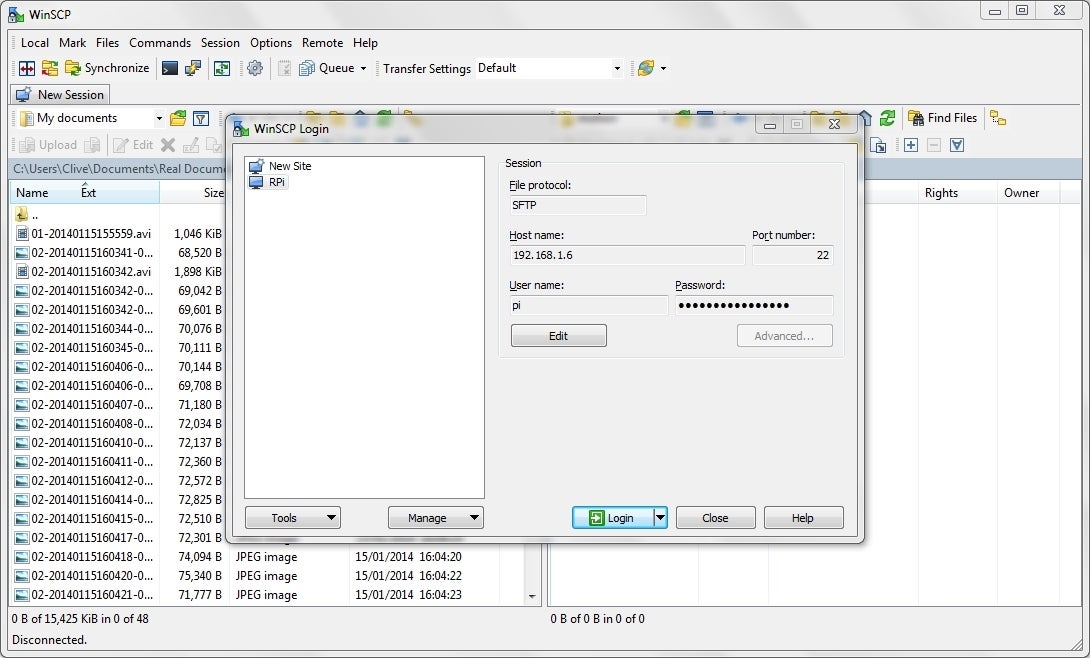
Use WinSCP to copy files from the Pi to your Windows PC
As the red LED on the Pi Camera Module can cause glare and reflections or even tip off a burglar, you might want to disable it once you know that Motion is working correctly. Type ‘sudo nano /boot/config.tx’ and add the line ‘disable_camera_led=1’ at the end of the file. Press Ctrl+X, then Y and then Enter to exit and save.
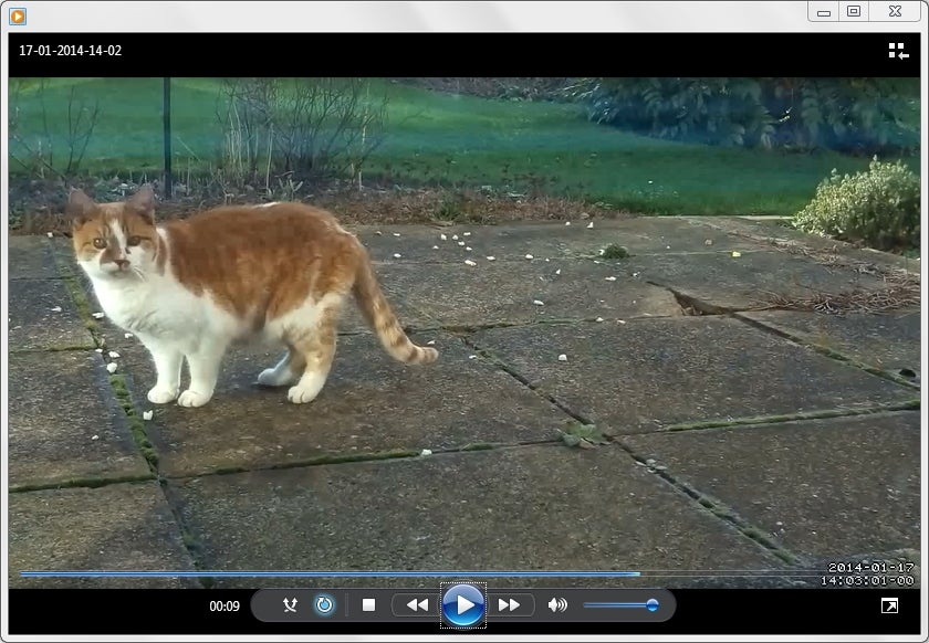
You never what kind of intruder your motion-powered Pi-cam will detect
More on Motion.conf
Motion has a hundred options to fiddle and play with in its lengthy configuration file; there are some we’d almost always change, some we might change if we had a certain task in mind, and others we might fiddle with if we had plenty of spare time and a very specific aim. Remember that you can skip to each setting using the Ctrl+W search tool of the Nano text editor; to edit the configuration file you need to type ‘nano /etc/motion.conf’.
| Setting | Comment |
| width 1280 | The Pi’s processor can only handle so much data per second, so you have to balance resolution with frame rate and bit-rate. The tweaked version of motion also typically hates resolutions that aren’t either 4:3 or 16:9 in aspect ratio. |
| height 720 | |
| framerate 10 | |
| ffmpeg_bps 400000 | |
| pre_capture 2 | Includes a number of frames in the final video before and after the motion itself was detected – 2 is a reasonable number, as too many puts too much strain on the Pi. |
| post_capture 2 | |
| max_movie_time 300 | The maximum time, in seconds, that any recording can be. You would use this setting to save storage space, but if you’re not bothered, leave it at 0 (infinite). |
| ffmpeg_video_codec msmpeg4 | Use the msmpeg4 setting to create videos that can be played in Windows Media Player. |
| output_pictures off | No pictures will be created, only a video |
| movie_filename %d-%m-%Y-%H-%M | Name the video file according to the convention dd-mm-yyyy-hh-mm |
| rotate 180 | We always seem to set up the camera upside down, check via the live-stream before changing this setting. |
Other options include ‘text_right’ if you don’t like the default date order, or ‘threshold’ if you find Motion is too trigger-happy. Trawl through the motion.conf file and you’ll see some very odd uses for Motion. For example, the ffmpeg_timelapse option allows you to start a timelapse video as soon as motion is detected (say, the builders turning up in the morning). The External Commands, Warning and Logging section even allows advanced coders to trigger certain actions once motion has been detected, an image has been created or a video has finished recording. Team Motion with some Smart Home kit and you could have the hall light automatically come on once someone approaches the front door, whether that be yourself or a nefarious interloper.